Project 2 in the pipelines - Full suspension XC 26er/650b frame

I like my hardtail as it is extremely fast, nimble and excellent for xco length races, but it can be a little harsh on longer rides. With aspirations of competing in longer events and one day riding the BC Bike Race (and other multi day stage races), I have decided to attempt to build a full suspension frame...

To begin with I have started researching the existing options available on the market and their respective suspension geometries - the two main bikes I looked at were the Scott Spark and Rocky Mountain Element, both of these are 29ers (apart from the spark with which they now make a 650b version too), but the basic kinematics and linkage design will be the same no matter the wheel size.

The Element RSL- the main inspiration for my bike 
I was advised to use the Linkage X3 software - and it turns out it's brilliant, it has allowed me to to design the exact pivot locations and how it affects the bikes handling. I have decided on a faux bar suspension linkage design (called 4 bar in Linkage X3 for some reason?), as it allows me to create a rigid swingarm and a lightweight arm to actuate the shock. I plan on 100mm travel, and using 26 inch wheels initially, but designing the frame with slightly variable geometry so I can put 650b later on.

The design of the geometry as of today.

I have got hold of a Pinnacle Arrow frame to use as a donor bike  - I'm yet to see it in person, but I hope to be able to use the dropouts and the bottom bracket shell. I will also look at the quality and shape of the carbon seatstay and see if it's worth using my frame. I may also use the headtube depending on whether it's moddable to a tapered design

A Pinnacle arrow - seems a shame to cut up such a nice bike - but it was cheap, and fits what I need!

I'll post the next update when I begin the making!


Full Suspension Frame - Part 2 - more designs by request

I have been asked if I could show some of the more detailed designs and the CAD that I have done for this and to explain the design process that I have used to get to them - so here goes.

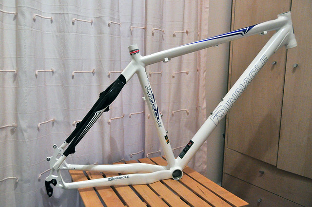
 So to start with I made a rough model of the front triangle (blue part) in NX8.5, but I made sure all the pivot points, BB, headset and dropouts were located in the right places. I then started to build the individual components up around this. My plan for the CAD model was more to get an idea of the spaces I will have available to locate the pivots, rather than design them.


The main pivot will be the most crucial as the majority of the torsional forces will be transmitted through it, my plan is to overbuild the area slightly so to be sure it holds up.


Here is a rough sketch of how I intend to do the main pivot - I plan on using two bearings housed in a steel insert that will be bonded into the frame, I will then have a 12mm axle that the swingarm will be attached to, which should hopefully be rigid enough! The blue signifies where I will put a nylon washer on each side to allow for tolerances to be slightly off without creating play.  

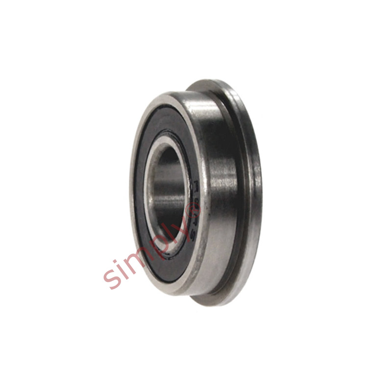
These are the bearings I hope to use - the flange should allow me to locate the bearings exactly where I want them without any complicated retention methods.


For the top linkages I intend to use mainly nylon bushes mainly for the sake of simplicity and saving weight, but also they are significantly cheaper to get hold of (about 50p each). The drawing below shows one half of the shock/linkage/chainstay joint, the red writing signifies the rough widths of each part - so 34mm for each side with a total width of 68mm, which I feel is the upper limit before you will start catching your knees in the case of an accident. I will use a standard shock mount from with a 10mm center hole to allow me to run a single shaft through the whole assembly. 


For the more simple linkages I will just use a simple nylon bushing, that I will put a 10mm steel bar through so should rotate nicely, and be really simple and cheap to maintain.

Any questions feel free to message me or comment on here and I will try to answer!

Full Suspension Frame - Part 3 - Building begins

As I have a couple of days off after my January exams, I decided I would come home to get started on the build. I ordered a piece of blue modeling foam 200x500x600mm as it was cheaper than a piece 70mm thick, and would leave me with plenty spare. So after about 20 minutes of cutting with the longest saw in the garage I finally had a piece 70mm thick as required.

This is the 1:1 scale template I will use to make the jig and cut the foam is now complete. I have opted to use a straight top tube and a tapered down tube, it will remain 65mm wide throughout it's length, but it will taper from 70mm at the top down to 50mm at the bottom bracket.

The tape I will be using to compress the carbon will be this green 30mm wide electrical tape, I have 240m which should hopefully be enough. I am using green as I found the black tape I used on the hardtail was hard to remove completely as it blended in with the carbon fibre when set.

The bottom bracket shell off the donor bike cleaned up pretty nicely, and comes in at 57g, which compared to the 97g bb shell  I used on my hardtail project is quite impressive.

For the headtube I have decided bond headset cups into a carbon tube, rather than to use a donor headtube, I'm using a superstar tapered headset as it has quite large flanges on the upper cup, and 25mm flanges for the lower cup, so a decent bond will be possible, this method should be about 75g lighter and no less durable.

For the seattube I have used a slightly cracked Boardman seatpost wrapped with a thin layer of tape as a mold, this is is the same method as I used on the hardtail.  

Here are all the pieces previously described now wrapped in carbon fibre and the green electrical tape - I will try to update asap with how they have come out.  


Full Suspension Frame - Part 4 - The Jig, The core and putting it together!

Today's building went well, I have been able to build the jig, make the foam core for the front triangle and assemble the BB shell, seattube and headtube into the frame with the first layers of carbon, below are the 3 pieces i left to set last night, all came out well, and the seatpost wasn't too hard to remove from the seatpost.


Here are the same parts in the positions they will be on the frame with the paper template ans the foam I made the core out of.

 The production stages of the foam core...


The jig is made up of a sheet of MDF which I have supported the components on- I have made the center line of the frame 15cm out from the MDF so I can reach behind it when laminating the carbon fibre.

 here I have placed the foam core in place ready to add the first layer of carbon to hold it all together.

And voila! the carbon will be left overnight to set and I will add some photos in the next update with how it has turned out, hopefully with the next pieces of the build too!.


Full Suspension Frame - Part 5 - Adding the main pivot and a few more layers.

Today's building has gone well, the work I did yesterday has set nicely and the frame was able to be removed from the jig to check the alignment.


 The headtube is shown here - it is currently just held on with only 2 layers of carbon, but that is plenty to be able to remove from the jig.


I added a jig mount for the main pivot point, it will be he in with about 5 layers of carbon as the majority of the force will be going through it.

Due to a request I have taken a few photos of the carbon lay up process - I wet the carbon cloth out on a flat sheet of wood using a foam squeegee to remove excess resin so to get the amount of resin for the best strength. I then lay the wetted cloth in position, and press it in place by hand.


All today's work is now taped up so will be setting over night, I have now got a total of 6 layers on the headtube, 3 on the seattube and 3 on the bottom bracket - will update soon with any progress!


Full Suspension Frame - Part 6 - Making the linkage and adding even more layers

The linkage I'm going to use is made out of 8*25mm aluminium, I have drilled 10mm holes in each side to remove a bit of excess weight, and I have a 5*20mm version I will try to see if I notice any difference in stiffness/strength - as that would be about 50g lighter. I intend to round the corners off and smooth the edges in the final version, but these are just the functional prototypes.

The bolts I'll be using to assemble this will be M6 stainless steel (cut to size), with nyloc nuts for extra security, I hope these will be strong enough, but I have left the scope to change to M8 if needed.

The dropouts I'll be using are off of the donor frame, they are the right shape for me to slightly enlarge the seatstay mounting holes to put the pivots in their place.

The metal inserts I'm using are 10mm steel tube for the internal sections of the pivots, 8*25mm aluminium bar for the swingarm/main pivot area and linkage, 5*20mm bar for the inserts in the shock mount, 14mm internal diameter aluminium tube for the linkage pivot and 22mm internal diameter tube for the main pivot.

Here is the next layer of tape and carbon, I have now got all the layers I intend to use on the headtube (8) and one short on both the Bottom bracket (7), and seatpost (3/4) - these will get added when I add both the suspension mounts. 

To remove excess resin I have pierced holes every 10-15mm, this should hopefully make a lighter stronger layup, and therefore frame.

Sadly these will probably be the last updates till late march as I'm now back at uni. 

Full Suspension Frame - Part 7 - jigging the swingarm

After a 2 month break I have finally been able to get going again on building the frame, looking at my previous work, it looks like I'm going to have to replace the main linkage pivot area of the frame due to a small problem with clearance of the front derailleur and the main pivot, but this shouldn't be too much of a problem as I can do it at the same time as the shock mount.


As can be seen here I have had to cut away a small area, this was due to it clashing with where the front mech will swing so I'm going have to recess it slightly


I have started to jig the foam for the swingarm, I intend to build it fully out of foam before I start to add carbon so I can perfect the geometry and make sure it doesn't contact the front triangle as it moves.


I'm hoping progress should be a bit quicker over the next week as it feels like I have got very little done over the past few days - and I'm hoping to have this done by the end of april.

Full Suspension Frame - Part 8 - Back a few steps

Today I have had to remove the main bearing mount due to having to make it about 3mm narrower due to clearance issues between the swingarm and the front mech/chainrings, I have also had to remove quite a bit of material from the non drive side to do this. Doing this was a bit of a last resort but will be necessary if I want to be able to run a double or triple chainring setup.


I have made a small amount of progress on the swingarm, I have now done the first layer of carbon around this end (with a thin layer of fibreglass to stop corrosion), so it will be ready to be attached to the chainstays by tomorrow. 


The rear shock I am going to be using initially arrived in the post today, along with a linkage from a Yeti ASR-sl, using a premade linkage will be stronger and lighter than making one myself, due to not having easy access to a milling machine, but in the future I hope to make one myself out of carbon.


Tomorrow I hope to make progress on the swingarm and hopefully the start the shock mount too.


Full Suspension Frame - Part 9 - starting to look like a bike!

The linkage is now attached and swinging freely (in the direction it's meant to!), this has allowed me to check the shock for fit and attach the shock mount to the frame. 


The mount for the linkage isn't particularly neat at the moment, but I will clean it up once I have tested that it is working well, as there is no point polishing it up incase I have to redo it. 


Here I have put the frame on it side to judge the angle for the mount, it will need to take a huge amount of force (about 2.5 times the force at the wheel) so this will have to be one of the strongest areas of the bike.


I intend to build this area up into a wedge shape to distribute the load along the top tube, but initially I have just used a small amount of resin to tack it in place.


The progress on the swingarm has been slightly slower than expected, this is mainly due to having to get the alignment right or the bike will track to one side. I also need it to be extremely stiff so I have been trying to get the layup as smooth as possible.


Full Suspension Frame - Part 10 - swingarm nearly done!

The majority of the work I did today was on the swingarm, although I did  build up a few layers around the shock mount too.


AS can be seen I have added a few layers of carbon to add strength to the shock mount, I have also used a small wedge of foam to smooth out the curve from the mount to the top tube. 


The rear swingarm is coming along nicely, as a few of you may have noticed, I have used the carbon seatstays from the donor frame as part of the swingarm, I have also made it asymetric, by having a taller stay on the non drive side, for added strength where there is no chain to interfere with it.


I have also added about 5 layers onto it so by tomorrow it should be nearly complete!


These are the aluminium inserts/pivots for the seatstays, I will bond them into the lower ends of the stays, I have had to recess the bolts so they don't foul on the brake rotor.